Geoteric’s Fault Expression is an intuitive and flexible tool that allows the user to produce fault attributes, blends and detect volumes in one simple workflow. By providing a range of different parameters, the results can be optimized for any size or style of fault. In this blog post, we will go through the process for successfully producing all of the products available in Fault Expression. Later posts will focus on optimizing for different types of faults.

Fault Expression
We begin by opening the Fault Expression window. Do this by going to the Reveal button in the top right of the main viewer.
We can then begin the workflow.
- Choose inline/Crossline/Timeslice for the preview.
- Choose which line number to preview.
- The Opacity slider can be used to fade between seismic and attributes.
- Optimize the Tensor attribute. This attribute looks at changes in amplitude.
- Check the three preset options.
- Select the tensor parameters that look best.
- Change the other two options with subtle variations on the chosen parameters. This can be done with the Fault Height slider on the right and the Fault Width slider on the bottom.
Example: If the middle “Width: 5 Height: 9” (5-9) attribute looks best, test a 5-5 in the top box and a 5-17 in the bottom box. In this way, you can confirm the optimal height. Use this same process to test the optimal width.
- Repeat this process until you have the optimal tensor attribute.
- Select the cyan box under the chosen attribute. This will assign it to the cyan channel of the blend.

- Repeat the optimization process for SO Semblance, which looks at phase by assigning the chosen attribute to the magenta box.
- Repeat the optimization process for Dip, assigning the chosen attribute to the magenta box.
- Select the CMY button to preview the blend.
- We can adjust the strength of the three channels with the Scaling sliders.

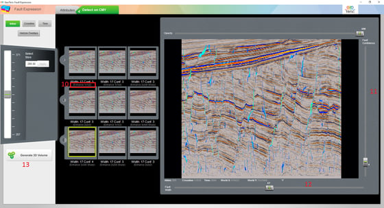
- Once we are satisfied with the blend, select the ‘Detect on CMY’ tab.
- The most important parameters in the Detect tab are the Enhance values. The larger these values, the larger the faults that will be picked. Click on each of the previews, and check the size of the faults being detected.
- Once you have found the best option, adjusting the fault confidence slider on the right will increase/decrease the number of faults picked.
- At the bottom is the fault width slider. Increasing this value should detect fewer, more significant faults. This effect is more subtle and should be the last thing you test.
- Once your testing is complete, hit the ‘Generate 3D Volumes’ button to run the full workflow.