

Dip and Azimuth volumes are used in several ways in Geoteric, from processes such as Noise Cancellation (SO FMH & SO Noise filters) to attribute generation (SO Semblance, SO Dip Derivative, SO Discontinuity, Flexure, etc...). The majority of these filters/attributes have the symbol SO in front of them, indicating they are Structurally Oriented.
In Geoteric, structurally oriented indicates that Dip and Azimuth volumes are needed to steer the filters/attributes along the regional geological trends of the input cube to give an improved result. The use of steering volumes guides the filters in the direction of the geology rather than the grid or in the direction of the noise in the volume.
In this blog post, an example of Noise Cancellation is used to show the importance of choosing the correct steering volumes for your purpose.
In this example, the SO FMH filter was calculated with the exact same settings, with the only difference being the Dip and Azimuth steering filter size. The SO FMH is an edge preserving filter which targets coherent noise, which can often be associated to acquisition footprint within seismic data.
The algorithm uses Dip and Azimuth volumes to guide the filter along the geology to accurately remove noise whilst preserving structural and stratigraphic edges. This study used Dip and Azimuth volumes which were calculated using small (5x5x7) and large (19x19x31) filters sizes.
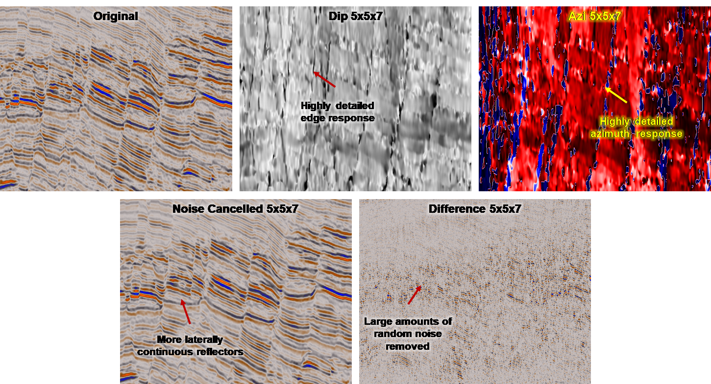
Figure 1. Noise Cancellation processed using a small-scale steering volume.
Figure 1 is the original data, the Dip, Azimuth, Noise Cancelled and difference volume using the small-scale steering volume settings. Notice the detail in the Dip volume, the small structural events and variation in dip. At first glance, the small-scale analysis (5x5x7) is doing a very good job at removing the noise and detecting a large number of the subtle structural elements and faults in the seismic cube.
Figure 2 shows the same volumes as figure 1. However, the Dip and Azimuth have been calculated using a larger filter size. In these volumes, it is possible to see the more general structures within the data such as faults and their associated fault blocks. Overall, both processes are doing a good job at removing noise from the dataset and enhancing the visualization capability of the seismic data.
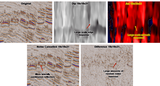
Figure 2. Noise Cancellation processed using a large-scale steering volume.
After the initial analysis of the two methods, there appears to be very minimal difference between the differing steering volume settings to the naked eye. As shown by the difference volumes in Figure 3, both processes are very similar or are removing the same amount of noise.
Only by creating a difference volume between the 2 difference volumes, it is possible to see the subtle difference between the two outputs. Now it is possible to observe that one of the processes is removing more information than the other along the fault planes. It is important to mention that the color bar has been compressed equally in these images for visualization purposes.
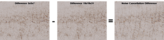
Figure 3. Comparing the difference volumes between the two noise cancellations show differences do occur when adjusting the Dip and Azimuth steering volume filter size.
Analyzing the results directly can help identify which steering volume is giving the better response. In the image below, a small scale structural lineament can be observed in the original reflectivity cube.
When a small-scale steering volume is used with this Noise Cancellation filter, this subtle flexure is identified as a noise artefact and subsequently removed. In contrast, the large-scale steering volume preserves the structural lineament.
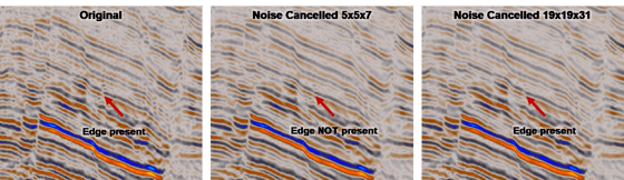
Figure 4. Optimizing the filter size can be crucial in preserving subtle structural features.
The primary purpose of a steering volume is to guide the filter through the data to identify (noise) artefacts in the data. By using a small steering volume, which may be very good at identifying small structural events and lineaments, it may not be optimized for identifying the larger structures clearly.
As shown in this instance, a small subtle flexure is interpreted as a noise artefact and subsequently removed from the data. When a larger steering volume is used however, it is possible to identify this event as part of a larger structure and retain the structural lineament.
The best location to test which Dip and Azimuth filters work best for each dataset can be in the Noise Expression tool (under the Condition tab). Here, it is possible to select a constant Noise Cancellation filter size and preview the response of varying the Dip and Azimuth steering filters on the fly. This ensures you get the most accurate noise cancellation for your data.
