

Polygons can be imported in ASCII format into Geoteric but also created on colour blends in the 2D colour blend viewer. The polygons created this way can be saved to the project tree and smaller polygons can be used to segment a colour blend based on opacity and then volumetric Geobodies can be extracted based on the segmented blend.
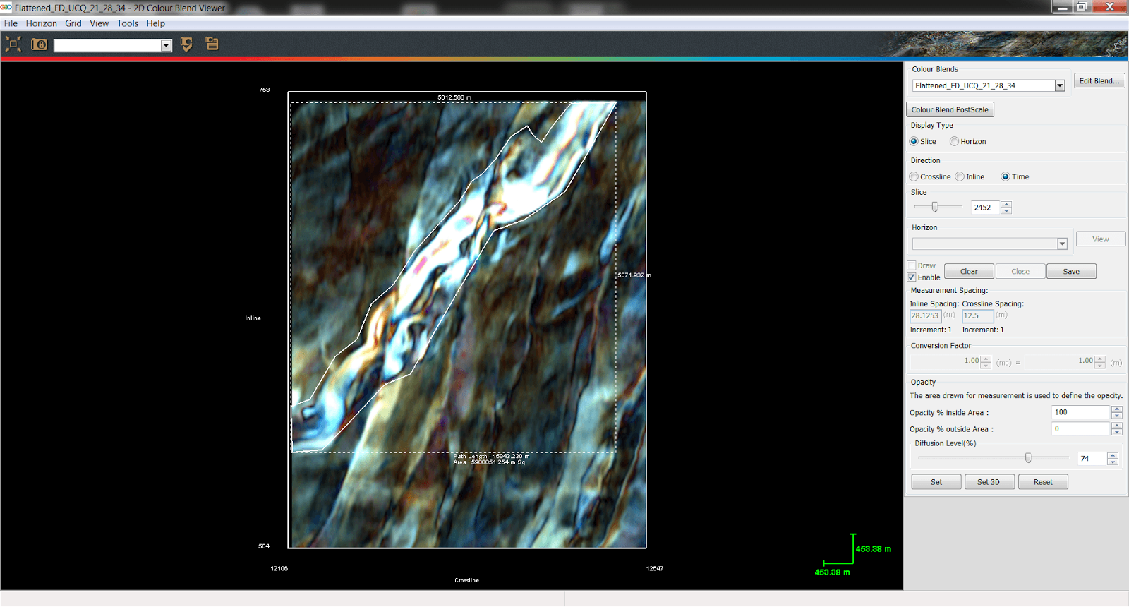
Accessed from the tools menu, the 2D Colour Blend Viewer allows the blend to be viewed as either horizon or time slice. The example below shows a polygon being created to broadly highlight the feature of interest on the channel complex. Once the polygon is saved it is automatically published to the main 3D viewer, where it will appear in the project tree under the Polygons folder.
 |
|
Figure 1: Channel feature is outlined with a polygon in the RGB blend and saved to the project tree. Metrics of the polygon can be seen by clicking the enable box.
|
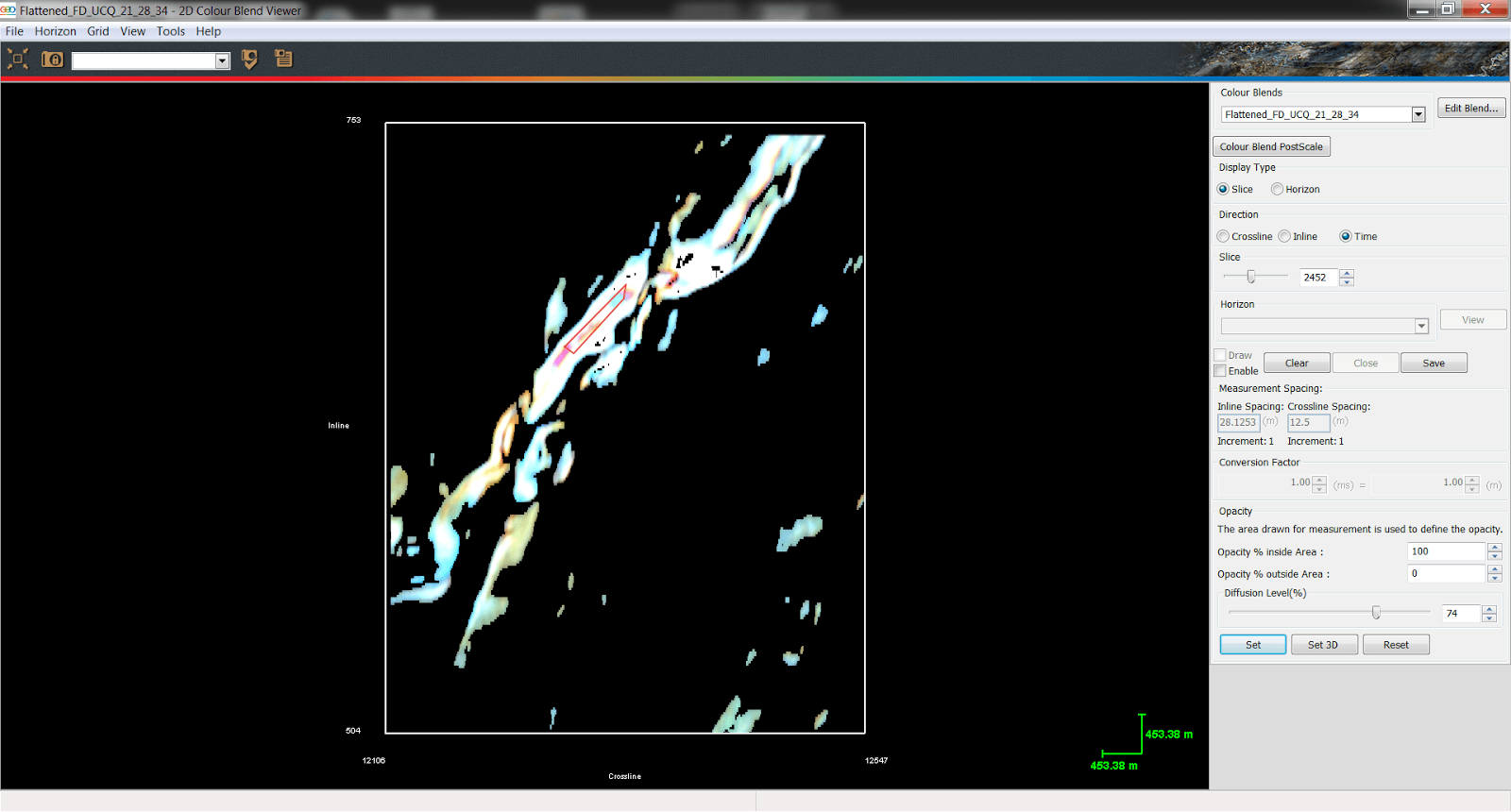
Alternatively, a polygon can be used to segment the colour blend. Just use a polygon to highlight a response in the blend and once the polygon is closed click ‘set’ to only show the responses similar to that in the polygon. The Diffusion Level (%) parameter then adjusts how much information is included in the segmentation. Higher percentages will include more information, while lower percentages will reduce the amount of data included in the segmentation.
 |
|
Figure 2: A small polygon is drawn highlighting the main response within the channel. The Diffusion level is then increased to give a fuller representation of the channel.
|
Once the user is happy with the result shown on the 2D slice, the segmentation can applied to the full 3D blend, just clicking on ‘Set 3D’. This will allow for the colour blend to be 3D rendered in the main 3D viewer (Figure 3). To do this, just go back to the 3D viewer, select the blend on the project tree and use the Render button on the proprieties area.
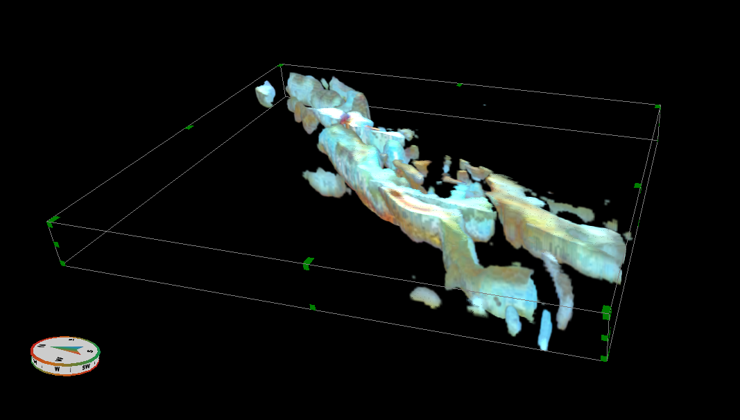 |
| Figure 3: The channel can be rendered in the 3D viewer as a 3D object |
The rendered blend can then be converted into either a binary or a Body Labelled volume.
 |
|
Figure 4: A volumetric geobody of the channel is then extracted by using the Body Labelling function. The rendered RGB blend is shown on the left and on the right we can see the rendered Body Labelled volume.
|
The Colour Blend Segmentation works particularly well when you have a unique or uniform response in the feature of interest. Where you have a variable response along one single feature then the Adaptive Geobodies will be the best option.
