The following workflow provides a fault proximity attribute, a volume that tells us how far the voxels in the seismic data set are from the detected faults. This attribute might be used as an input in different scenarios where distance from a fault or fault zone is needed (e.g. planning of a well path or hydraulic fracking).
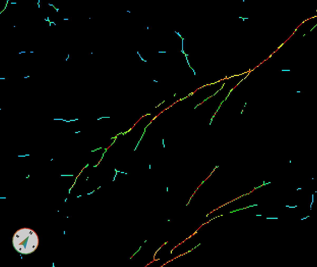
The starting point of the workflow is a Fault Detect volume. The values in a fault detect volume represent significance levels: the higher the value the higher the likelihood that a certain voxel is actually a fault. Zero values indicate non-fault voxels. We will use these zero value voxels.
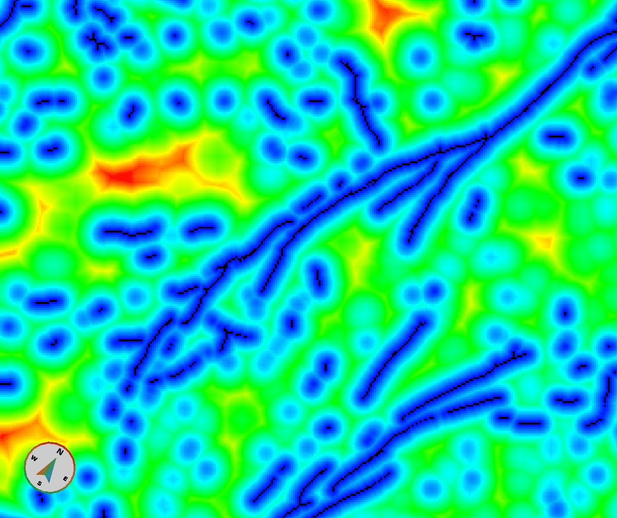
Next step is to generate a Thickness volume (Processes and Workflows > GeoBodies) using the FaultDetect volume as your input. We can choose to include all detected faults or set a threshold for excluding the low confidence fault segments, using either the opacity curve or a threshold value. For this example all fault segments were taken into consideration (threshold parameters: lower 0, upper 10). The operation was set to Distance, the direction to 3D. The result – Fault Proximity – is shown in the next image. Please note that Interpolation is turned off.
The values in this volume stretch over the dynamic range of the data type from zero (the faults that were not excluded in the previous step) to the maximum positive value (32766 in this case for signed 16bit data). When 3D Distance option of Thickness is used, GeoTeric determines the true Euclidean distance of each voxel from the nearest boundary voxel (i.e. any value higher than the threshold) and then linearly scales the distance values with a scaling factor to ensure that the whole dynamic range is used. Please note that the distance calculation uses voxels as units.
An approximate calibration of this volume can be achieved by determining the scaling factor. With interpolation turned off zoom in on a fault very closely and hover the mouse over a voxel right next to a fault segment (the sides of the voxels should touch each other, not their corners). The value of the voxel is shown in the bottom line of GeoTeric and this is the value used to scale the voxel distance with. If we divide the Fault Proximity with this scaling factor, we get the distance in voxel units. Please remember that GeoTeric uses integer numbers only, so it’s worth multiplying the Fault Proximity by 10 or 100 before dividing it with the scaling factor.
It is more challenging to determine the relation between a voxel and the actual physical distance it represents. The grid spacing can be uniform or non-uniform, and the actual vertical size of a voxel also changes along the Z axis, at least in time domain data. The best calibration can be obtained with uniform grid spacing and within a restricted stratigraphic unit where a constant interval velocity can be presumed. But remember, it will only be a rough estimate.
(by Peter Szafian, GeoTeric)