
Why do Iso-Proportional Slicing (IPS) in GeoTeric?
Iso-Proportional Slicing can be utilised in GeoTeric to analyse seismic data in a way that is conformant or proportional to the geology, allowing:
-
Rapid analysis of stratigraphic packages in a horizon consistent manner.
-
Visualise attributes in one stratigraphic layer when there is highly variable structure.
-
Anomalies in the packages can be quickly identified and cross checked with the seismic.
-
Generates attribute maps at intervals spaced between two non-parallel horizons.
-
Rapid attribute screening over targeted intervals of interest.
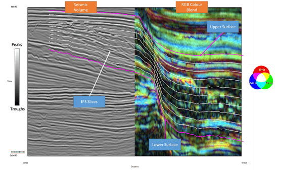
Iso-Proportional Slicing can be done on volumes (seismic reflectivity or attributes) and on colour blends (Frequency Decomposition or AVO RGB Blends for example). For a more in depth case study from the Taranaki Basin, NZ, click here: http://www.geoteric.com/uploads/downloads/segam2016-Depositional_History_Cognitive_Interp_GeoTeric.pdf
Click here for video: https://youtu.be/0lBL6EGNPdc
How to create Iso-Proportional Slices for Horizon Packs
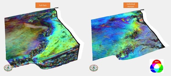
Horizon Packs allow the interpreter to rapidly scan through horizon slices, with a volume or colour blend mapped to the horizons, in the main 3D viewer. These can be created from IPS slices in addition to surfaces imported or interpreted in GeoTeric.
To create them in the IPS tool, select “dual horizon mode” and increase the number of slices to the maximum, which is 20. This will lead to a very tight Horizon Pack which will allow for more information to be revealed when screening.
Since any attribute can be mapped to the IPS slices generated, if the horizons are generated for the Horizon Pack, it does not matter which IPS attribute is generated, but one must be selected for the process to run.
Once the slices have been processed and generated in the map viewer, click on export data. Out of the two options available, select Export Iso-Proportional Slice Boundary Horizon(s). This is because the centre horizons are not required (but still can be used if the interpreter wishes). After the slices have been exported to the project tree in the main 3D window, select all of them, right click and select “Create Horizon Pack”.
Colour Blends and Attribute volumes can then be data mapped on to the Horizon Pack and scrolled through by the interpreter manually or by pressing the play button to do so automatically. The results can then be quickly exported as screenshots or as a video, if you are running Windows 10.
Click here for video: https://youtu.be/JTZ03yqIylA
What do the different IPS Attributes show me?
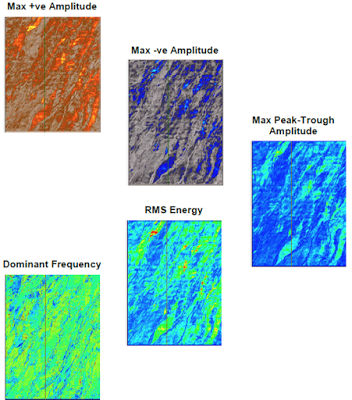
- Maximum +ve Amplitude is the largest positive value.
- Maximum -ve Amplitude is the largest negative or smallest value.
- Maximum Peak-Trough Amplitude is the greatest difference between adjacent peak-trough pairs.
- RMS Energy is the sum of the squares of the values in the trace segment.
- Dominant Frequency is (scale factor/T), where T is the largest period in the trace segment, measured from the zero crossings. Note this attribute is only applicable to reflectivity or signed data.
- Slice Thickness is the number of points in the trace segment: this is only available for the Dual Horizon mode as it is always the same for the other two modes.
Click here for video: https://youtu.be/lIKKXVHYypk
Colour Blend or Volume - What is the best input to use for IPS analysis?
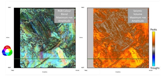
When using a volume such as seismic reflectivity, the positions of the IPS slices can be seen and aligned with much more clarity as opposed to a blend. The IPS attributes which can be generated are also all completely appropriate to apply on seismic data: hard and soft events, as peaks and troughs can be identified and differentiated by using the Maximum +ve Amplitude and Maximum -ve Amplitude.
When a Colour Blend is used for the analysis, each attribute will be calculated for each of the colour channels individually, and then re-blended. Colour Blends only utilise positive values in each of the magnitude volumes, therefore there are no peaks and troughs in them. Because of this, the Maximum -ve Amplitude attribute will only show the smallest value, not negative values between two slices. Using the Maximum -ve Amplitude in a blend however can sometimes reveal subtle features which would not be obvious when looking at the highest amplitudes. The Dominant Frequency and Slice Thickness attributes on the other hand cannot be applied to the blend.
Click here for video: https://youtu.be/7bnxlvvEmjE
How can I create an Iso-chore map in GeoTeric?
The IPS tool also allows for Iso-chore maps to be created using a thickness attribute. This can only be done in the dual horizon mode. Choose your seismic reflectivity volume as the input and after selecting the upper and lower surfaces; make sure the number of slices is 1 and tick the “Slice Thickness” attribute only. The more attributes and slices selected means the longer the processing will take. Click on “process” and then go to “Export Data”. Select “Export Iso-Proportional Slice Centre Horizon(s) with Map Data Attached” and make sure that the “Slice Thickness” is ticked. Once the slices have been output into the project tree, you will be able to select “Iso-Proportional Attribute” in properties after selecting a slice. Choose the “Slice Thickness” and then it will be mapped on the surface.
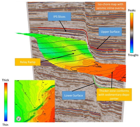
The user is free to add additional information such as contour lines to aid in the visualisation of the iso-chore maps. Such maps in a geological setting like this can be effective at highlighting features in terms of thickness.
Click here for video: https://youtu.be/PVyQdyuQHYM
